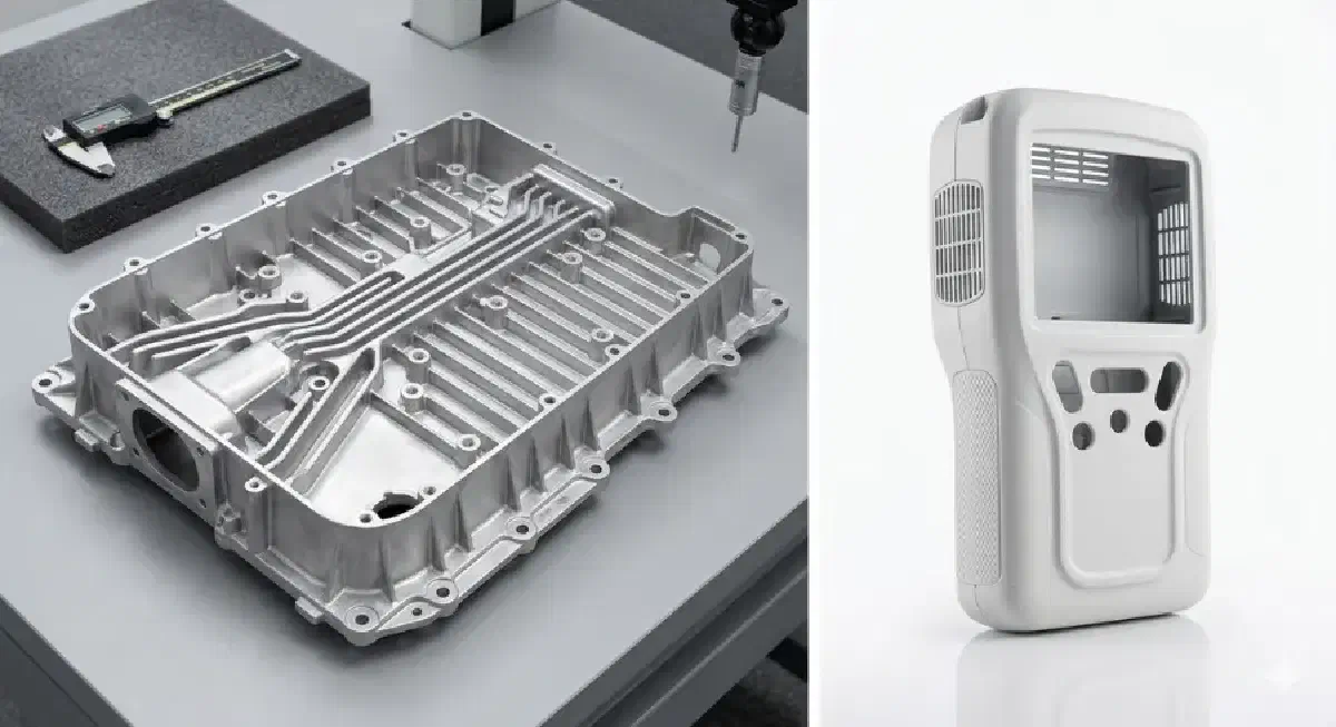
CNC Machining for Die-Cast Components: Allowance, Datums and Achievable Tolerances#
High-pressure die casting produces a near-net-shape blank. It does not produce the sealing faces, threaded holes, bearing seats or assembly datums that a finished part needs. CNC post-machining is where those functional features are created, and the decisions that govern it are taken on the drawing — not on the shop floor. This page is written for design engineers, process engineers, sourcing managers and quality engineers who need to specify a cast-and-machined component, decide what belongs on the casting drawing versus the machining drawing, and understand what a tolerance statement actually commits to.
CNC machining of die-cast aluminium and magnesium components differs from machining wrought billet. The blank already has a cast skin, a parting line, draft angles, ejector marks and internal stress from solidification. Removing the skin can expose subsurface porosity; clamping on a curved cast surface can distort a thin wall; and every additional setup accumulates positional error. These are design and planning questions, and they are cheapest to answer before the die is built.
Why post-machining determines part function#
A casting can hold its general shape within the process capability of HPDC, but the interfaces that determine whether a part assembles are machined: flatness of a sealing face, position of a dowel hole, perpendicularity of a bearing bore to its mounting plane, and thread depth in a boss. Separating “as-cast” from “as-machined” dimensions on the drawing prevents a supplier from treating a cast surface as a functional datum. For sourcing teams, this separation is also the basis of a meaningful quotation: it defines how many setups, fixtures and inspection steps the part actually needs.
From the cast blank to a machining allowance#
Machining allowance (stock allowance) is the material deliberately left on the casting so the tool can cut below the cast skin in one continuous pass. Too little allowance leaves skin or oxide inclusions on a sealing face; too much increases cycle time, tool load and heat input, which matters particularly on thin walls. The allowance must be planned together with gating, parting-line position and ejector placement, because the surface used as the first datum must be stable and repeatable. A DFM review that moves an ejector mark away from a datum pad is often worth more than any change to cutting parameters.
Datum strategy and critical dimensions#
A datum scheme A|B|C ties the finished-part geometry to the same reference frame used for inspection. On cast components the primary datum is usually a broad, machined pad; the secondary and tertiary datums constrain rotation and translation with holes or edges. Single-setup machining reduces stack-up, but where a second setup is unavoidable, the drawing should state which geometric tolerances are checked in which setup. Functional dimensions — sealing-face flatness, bore position, thread location — should be dimensioned from the datums, not from cast edges. ISO 1101 / GD&T notation is the clearest way to express this for a global supply chain.
Feature design: bosses, ribs, holes, threads and sealing faces#
Bosses need enough local mass to support thread engagement without sinking or porosity at the root; ribs should stiffen without creating hot spots that feed shrinkage; and cored holes should be sized so the drill or tap removes a predictable amount of material. Sealing faces need a continuous machined land with a defined surface finish and no ejector marks inside the seal path. Wall thickness of approximately 1.0–1.2 mm is a project-dependent guide for thin-wall HPDC work — the achievable value depends on the alloy, part geometry, flow distance and the specific project conditions, and must be confirmed in DFM rather than assumed.
Achievable tolerance and what governs it#
A tolerance of ±0.01 mm can be achieved on defined features under appropriate post-machining conditions. The achievable tolerance depends on part geometry, material, machining process and setup, datum strategy, inspection method and project-specific requirements; it is confirmed during drawing and DFM review — not a blanket value for every part or every casting.
This distinction matters commercially. A tolerance is a property of a defined feature on a defined part, produced by a defined process and verified by a defined method — it is not a general capability statement. Thin walls deflect under clamping force; magnesium alloys expand more than aluminium with temperature; a feature reachable only in a second setup inherits the error of the first; and a measurement taken with a different method or at a different temperature can legitimately produce a different result. Requests for a single “machine capability” number should therefore be replaced with a per-feature tolerance table and an agreed inspection method.
| Factor | Why it changes the achievable tolerance | What to specify at RFQ |
|---|---|---|
| Part geometry | Thin walls, overhangs and deep cavities deflect under cutting and clamping loads | Wall thickness, rib layout, unsupported spans |
| Material | A357 aluminium and AZ91D/AM60B magnesium differ in thermal expansion, chip formation and stiffness | Confirmed alloy grade and condition |
| Machining process and setup | Each additional setup adds positional error; tool reach affects stiffness | Which features are machined in which setup |
| Datum strategy | Inconsistent datums between casting, machining and inspection create apparent drift | Datum A|B|C and geometric tolerances on the drawing |
| Inspection method | Results depend on method, temperature, fixturing and sampling plan | Agreed measurement method and acceptance criteria |
| Project requirements | Series volume, documentation and sampling change the process plan | Annual volume, prototype vs series, documentation scope |
Machining A357 aluminium and AZ91D / AM60B magnesium#
A357 is the confirmed aluminium casting alloy; AZ91D and AM60B are the confirmed magnesium casting alloys. Their machining behaviour is not interchangeable. Magnesium has lower density and higher thermal expansion, cuts with lower forces, and produces fine chips that require disciplined housekeeping and appropriate fire-safety precautions — a general industry consideration, not a claim about any specific factory setup. AM60B is generally selected where ductility and impact energy absorption matter, while AZ91D is the widely used general-purpose casting alloy with a balance of castability and strength. Cutting parameters, coolant choice, tool geometry and chip evacuation should be set against the actual grade and the part, and the appropriate safety measures reviewed with the machining supplier.
Surface finish, deburring and post-processing#
Surface finish is a drawing requirement, not a universal promise: Ra targets should be attached to the specific functional face that needs them. Deburring strategy belongs in the process plan too, because burrs on a sealing land or in a threaded boss cause assembly problems that are expensive to find after coating. Confirmed secondary processes include Shot Blasting and Anodizing; other surface treatments sometimes discussed for magnesium — conversion coatings, e-coating or micro-arc oxidation — are general industry options whose suitability, corrosion performance and availability must be evaluated per project. No corrosion-resistance claim should be made for bare magnesium without a defined treatment.
| Topic | As-cast condition | After post-machining | Project-dependent decision |
|---|---|---|---|
| Surface | Cast skin, parting line, ejector marks | Machined functional faces | Ra target per face, deburring method |
| Dimensional reference | Cast edges and draft surfaces | Datum A|B|C machined pads | Which features are inspected in which setup |
| Appearance / protection | As-cast finish | Shot Blasting, Anodizing available | Treatment choice, masking of machined faces |
| Documentation | Casting drawing | Finished-part drawing + inspection plan | Inspection and documentation scope per project |
Integrating casting and CNC in one program#
Keeping HPDC and post-machining in one program shortens the feedback loop: a machining problem found at first article can be fixed by changing gating, draft, allowance or ejector position in the die rather than by adding an extra machining operation. It also removes a vendor interface, so dimensional disputes do not bounce between a foundry and a machine shop. Integration is a coordination benefit, not a quality guarantee — the inspection plan, sampling and acceptance criteria still have to be agreed explicitly for the project.
Inspection scope and project quality requirements#
First-article inspection, PPAP documentation and CMM-based dimensional verification are project-specific deliverables to be agreed at RFQ stage, not automatically included capabilities. What is required depends on the customer’s quality system, the end application and the drawing: which characteristics are measured, with what method, at what frequency, and with what records. Stating the scope up front avoids both over-specification and gaps at first article. Kingship works to agreed project requirements; no current validity is claimed for IATF 16949 or ISO 9001 certificates, and quality-system expectations are handled as “aligned with” requirements where applicable.
| Quality topic | How to treat it in an RFQ |
|---|---|
| First-article inspection | State whether a first-article report is required and its format |
| PPAP / documentation | Define the submission level and which documents are in scope |
| Dimensional verification | Name the characteristics, method, sampling and acceptance criteria |
| Change control | Agree how drawing revisions and die modifications are approved |
| Traceability | State lot, material and inspection record requirements |
Applications and component-specific considerations#
Housings and enclosures need flat sealing lands and positional accuracy between the lid interface and internal mounting bosses. Gearbox and transmission covers combine large flat faces with deep bores, so distortion after unclamping is a real risk. EV and motor housings add thermal and, in some designs, leak-tightness requirements to the machining plan. Brackets and fixtures are often simple in shape but tolerance-sensitive at the interface. Precision rotors and similar rotational parts need concentricity referenced to a single machined datum. In every case, the component’s functional requirements — not a generic machine specification — determine the machining strategy.
| Component type | Machining-critical features | Typical drawing focus |
|---|---|---|
| Housings / enclosures | Sealing land flatness, lid hole position | Flatness, position, surface finish |
| Gearbox / transmission covers | Bore concentricity, large-face flatness | Perpendicularity, datum scheme |
| EV / motor housings | Thermal faces, leak-tight interfaces | Flatness, Ra, agreed leak-test scope |
| Brackets / fixtures | Interface hole position | Position tolerance from datum A|B|C |
| Precision rotors | Concentricity, balance-related surfaces | Runout, single-datum machining |
Selecting a cast-plus-CNC supplier#
Ask how the supplier handles the casting-to-machining interface: who defines the allowance, whether the die design is reviewed against the finished-part drawing, how the first setup is referenced, and how a drawing revision propagates to both the die and the CNC program. Also ask what inspection and documentation the supplier can support for your specific project. A supplier who discusses datums, allowance and DFM before quoting machine hours is usually one who has thought about the part rather than the process list. For related capabilities see magnesium die casting, semi-solid rheocasting and die casting tooling.
RFQ: what to provide for a usable quotation#
The fastest route to a comparable quotation is a complete technical package. Missing GD&T or an undefined inspection scope is the most common reason two quotes for the same part are not comparable.
| RFQ input | Why it is needed |
|---|---|
| 3D model (STEP / IGES) | Defines geometry for DFM, fixture and tool-path review |
| 2D drawing with GD&T and datum A|B|C | Defines which features are functional and how they are verified |
| Alloy (A357 / AZ91D / AM60B) | Determines cutting behaviour, thermal and safety considerations |
| Annual volume and lot size | Determines process plan, fixturing and amortisation |
| Target tolerances per feature | Distinguishes critical from non-critical dimensions |
| Surface finish (Ra) per face | Determines finishing and post-processing steps |
| Inspection and documentation scope | Determines first-article, sampling and records |
| Prototype or series | Determines whether bridge or production tooling is appropriate |
Send the package through the contact / RFQ page and the drawing and DFM review will identify which tolerances need confirmation, where allowance should be added, and what inspection plan the project requires.