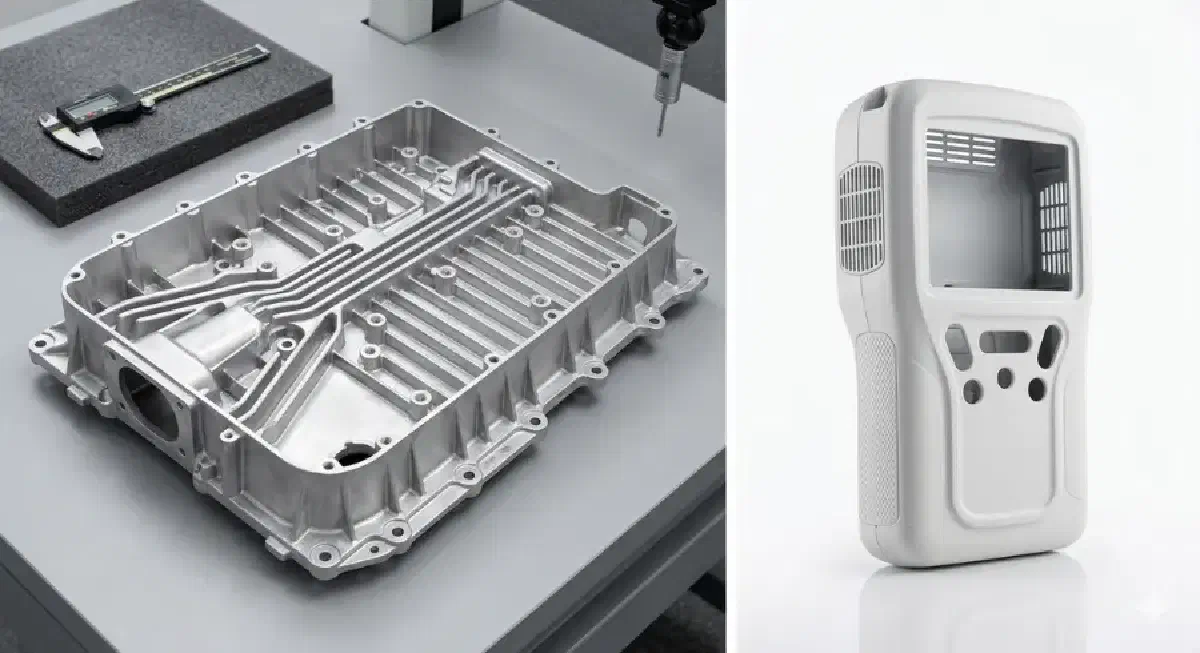
Die Casting Tooling: DFM, Tool Configuration and Project-Dependent Tool Life#
A high-pressure die casting die is the single largest fixed cost in a casting program, and most of the part’s manufacturability is decided before steel is cut. Gating and venting determine fill behaviour, cooling layout determines cycle time and distortion, and draft, fillets and ejector placement determine whether the cast blank can be machined reliably afterwards. This page is written for design engineers, process engineers, sourcing managers and quality engineers who need to specify and evaluate a die — including what a “tool life” number can and cannot mean.
The confirmed casting machine range is 400T–3000T, with A357 as the confirmed aluminium casting alloy and AZ91D / AM60B as the confirmed magnesium casting alloys. Tooling decisions are made against those process conditions and against the finished-part drawing, not against a generic capability list.
Tool life is project-dependent, not a fixed specification#
Tool life is not a fixed Kingship guarantee or standard specification. Actual tool life is project-dependent and is influenced by tooling design, tool material, the casting alloy and process, operating conditions, maintenance, and the acceptance requirements for the part. Figures sometimes quoted in general industry literature (for example 100k–500k shots for hot-work die casting tools) are general technical context only — they are not a Kingship performance figure, and no Kingship-specific historical tool-life performance is claimed here. For a specific program, expected tool life is discussed during DFM and sampling against the actual alloy, cavity geometry, thermal cycling, maintenance plan and the acceptance criteria agreed in the RFQ.
| Factor | How it influences tool life | What to define at RFQ |
|---|---|---|
| Tooling design | Gating, overflow, venting and cooling layout govern thermal and mechanical load on the cavity | Part geometry, expected thermal hot spots |
| Tool material | Hot-work die steel grade and heat treatment determine resistance to thermal fatigue and wear | Grade and treatment per project |
| Casting alloy and process | A357 aluminium and AZ91D/AM60B magnesium differ in melt temperature, soldering tendency and thermal load | Confirmed alloy and process conditions |
| Operating conditions | Cycle time, melt temperature, die temperature, lubrication and clamping force | Agreed process window |
| Maintenance | Preventive maintenance, spare inserts, reconditioning and surface condition tracking | Maintenance plan and responsibilities |
| Acceptance requirements | The dimensional and surface criteria that define when a cavity is no longer acceptable | Drawing tolerances, surface criteria, sampling plan |
Because these factors interact, a single number cannot be quoted as a contractual life for an unquoted part. The useful commercial question is not “how many shots does the tool last?” but “what is the maintenance and replacement plan for this part, at this volume, with these acceptance criteria?”
DFM-led die design#
DFM review happens before tool manufacture and again before steel cutting. It checks draft angles, fillet radii, wall transitions, rib and boss geometry, trapped features, ejector positions and parting-line location — then feeds the result back into the part drawing where a small change removes a large manufacturing risk. For thin-wall structural castings, a wall thickness of approximately 1.0–1.2 mm is a project-dependent guide: the achievable value depends on material, geometry, flow distance and project conditions. Deciding allowance for post-machining at this stage is essential, because the first CNC setup needs a stable cast datum.
| DFM topic | Decision made before steel cut | Consequence if decided late |
|---|---|---|
| Parting line | Where the die halves separate | Draft and flash affect datum stability |
| Gating / overflow | Fill pattern and air evacuation | Gas entrapment, porosity on machined faces |
| Cooling layout | Thermal balance and cycle time | Distortion, thermal fatigue of the cavity |
| Ejector placement | Where marks appear on the blank | Marks inside sealing lands or datum pads |
| Machining allowance | Stock left for CNC | Excess cycle time, or cast skin left on functional faces |
| Draft and fillets | Release and stress concentration | Ejection damage, hot spots, cracks |
Cavity count, cycle time and annual volume#
Cavity count is a commercial and technical trade-off, not a fixed offering. More cavities raise output per shot but increase die size, complexity and the risk of cavity-to-cavity variation; fewer cavities simplify validation and reduce tool cost. The decision is made against annual volume, part size within the 400T–3000T machine range, cycle time and the sampling plan. A bridge or prototype tool can shorten time-to-first-part when a program needs validation parts before committing to a hardened production die.
| Cavity strategy | When it is considered | Main trade-off |
|---|---|---|
| Single cavity | Low volume, large part, early validation | Lowest tool cost, highest piece cost |
| Multi-cavity | Stable high-volume series | Higher tool cost, output per shot, cavity consistency control |
| Family / shared tool | Related parts with compatible geometry | Reduced tooling spend, more complex change control |
| Bridge / prototype tool | Validation before series commitment | Faster first article, shorter life by design |
Fill, cooling and solidification review#
Fill and solidification behaviour is reviewed before tool manufacture so that gating, venting, overflow and cooling channels are laid out deliberately. The aim is to reduce air entrapment, control shrinkage in thick sections and keep the die thermally balanced. Simulation tools are one input to this review; the decision always rests on the part drawing, the confirmed alloy and the agreed process window. Where a part will be CNC-machined afterwards, the review also identifies where subsurface porosity could be exposed on a sealing face — a reason to coordinate tooling and machining planning early rather than sequentially.
Tool steel and surface condition#
H13 hot-work tool steel and SKD61 are common hot-work die steel grades used across the industry; the grade and heat treatment for a given tool are selected per project against the casting alloy, expected thermal cycling and cavity geometry. Surface condition of the cavity — including any treatment, polishing and reconditioning — affects both part surface and tool maintenance intervals. No specific grade, treatment or life is presented here as a verified Kingship standard; selection is confirmed during RFQ and DFM review.
Sampling, first article and dimensional review#
Tool tryout and sampling are where the DFM assumptions are tested. The first-article inspection scope, the characteristics to be measured, the measurement method, the sampling plan and the documentation to be supplied are project-specific items agreed at RFQ stage. PPAP tooling documentation, first-article reports and CMM-based dimensional verification are examples of deliverables whose scope must be defined by the customer’s quality system and the drawing — they are not automatically included capabilities. Kingship works to agreed project requirements; no current validity is claimed for IATF 16949 or ISO 9001 certificates.
| Sampling / quality item | How it is defined |
|---|---|
| First-article inspection | Format and characteristics agreed per project |
| PPAP / documentation | Submission level and document list agreed per project |
| Dimensional verification | Method, characteristics, sampling and acceptance criteria |
| Tooling change control | How drawing revisions and die modifications are approved |
| Maintenance records | Shot counts, cavity condition, insert replacement — as agreed |
Maintenance and lifecycle planning#
A tool’s useful life is managed, not merely endured. Preventive maintenance schedules, spare inserts, polishing and reconditioning keep cavities within the agreed acceptance criteria for as long as the project requires. Planning maintenance intervals and responsibilities at RFQ avoids ambiguity later: who tracks shot counts, who holds spare inserts, and what surface or dimensional condition triggers reconditioning. These are project agreements, not a promise of a fixed shot count.
Lead time and cost drivers#
Tool cost and lead time are driven by cavity count, steel grade and treatment, part complexity, the number of sampling iterations, and the agreed inspection and documentation scope. The cheapest die is rarely the cheapest program: a gating or cooling decision made too quickly is paid for in cycle time, scrap and downstream machining. A comparable quotation requires the same technical package to be sent to every supplier.
| Cost / lead-time driver | Why it matters |
|---|---|
| Cavity count and die size | Tool steel volume, machining time, machine tonnage |
| Part complexity and cores | Additional slides, inserts and maintenance points |
| Steel grade and treatment | Material cost, lead time, thermal-fatigue behaviour |
| Sampling iterations | Time to first article and validation loops |
| Documentation scope | First-article, PPAP and inspection deliverables |
| Change control | Drawing revisions after steel is cut |
Integrating tooling with casting and CNC#
Because tooling, HPDC and post-machining interact, keeping them in one program shortens the feedback loop: a problem found at first article can be fixed by changing gating, draft, allowance or ejector position rather than by adding a machining operation. This is a coordination benefit, not a quality guarantee — the inspection plan and acceptance criteria still have to be agreed explicitly. See CNC machining, magnesium die casting and semi-solid rheocasting for the related process pages.
RFQ: what to provide for a tooling quotation#
| RFQ input | Why it is needed |
|---|---|
| 3D model (STEP / IGES) | Geometry for DFM, gating and cooling layout |
| 2D drawing with GD&T and datum A|B|C | Functional features, tolerances and verification basis |
| Casting alloy (A357 / AZ91D / AM60B) | Melt conditions, thermal load, tool steel choice |
| Annual volume and lot size | Cavity count, tool class and amortisation |
| Target tolerances and surface finish | Machining allowance and cavity surface requirement |
| Prototype / bridge or production tool | Determines tool class and validation path |
| Inspection and documentation scope | First-article, sampling and records |
| Maintenance and spare-parts expectations | Lifecycle plan and responsibilities |
Send the package through the contact / RFQ page; the DFM review will identify the gating, cooling, allowance and sampling questions that need answers before steel is cut.